|
#1
July 4th, 2014, 10:08 AM
| |||
| |||
| Diagram for Mobile Jammer Circuit
Please provide me Simple Mobile Phone Jammer Circuit Diagram as soon as possible ? Here I am giving you Simple Mobile Phone Jammer Circuit Diagram in an image format attached with it . Part List Component No: Value Usage R1 100R Emitter loading R2 39k Base Biasing C1 15 pf Frequency Generating C2 4.7pf Feedback C3 4.7pf Feedback C4 102pf Noise Reduce C5 1MF Coupling C6 2.2pf Coupling C7 103pf Decoupling Q1 BF 494 Amplification L1 22nH Frequency Generating 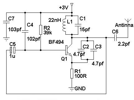  Last edited by Neelurk; February 26th, 2020 at 11:07 AM. |