|
#2
June 20th, 2016, 12:38 PM
| |||
| |||
| Re: Eq Pedal Schematic
Hey Ankur!!! The Boss GE-7 Equalizer pedal adjusts the harmonic contents of an instrument in 7 separate bands ranging from 100Hz to 6.4kHz, with a boost/cut 15dB per band. The additional Level control knob helps you to set a different volume for normal and effect sound (or to use the pedal only as a gain booster). Here I am providing you Boss GE-7 Equalizer pedal schematic diagram 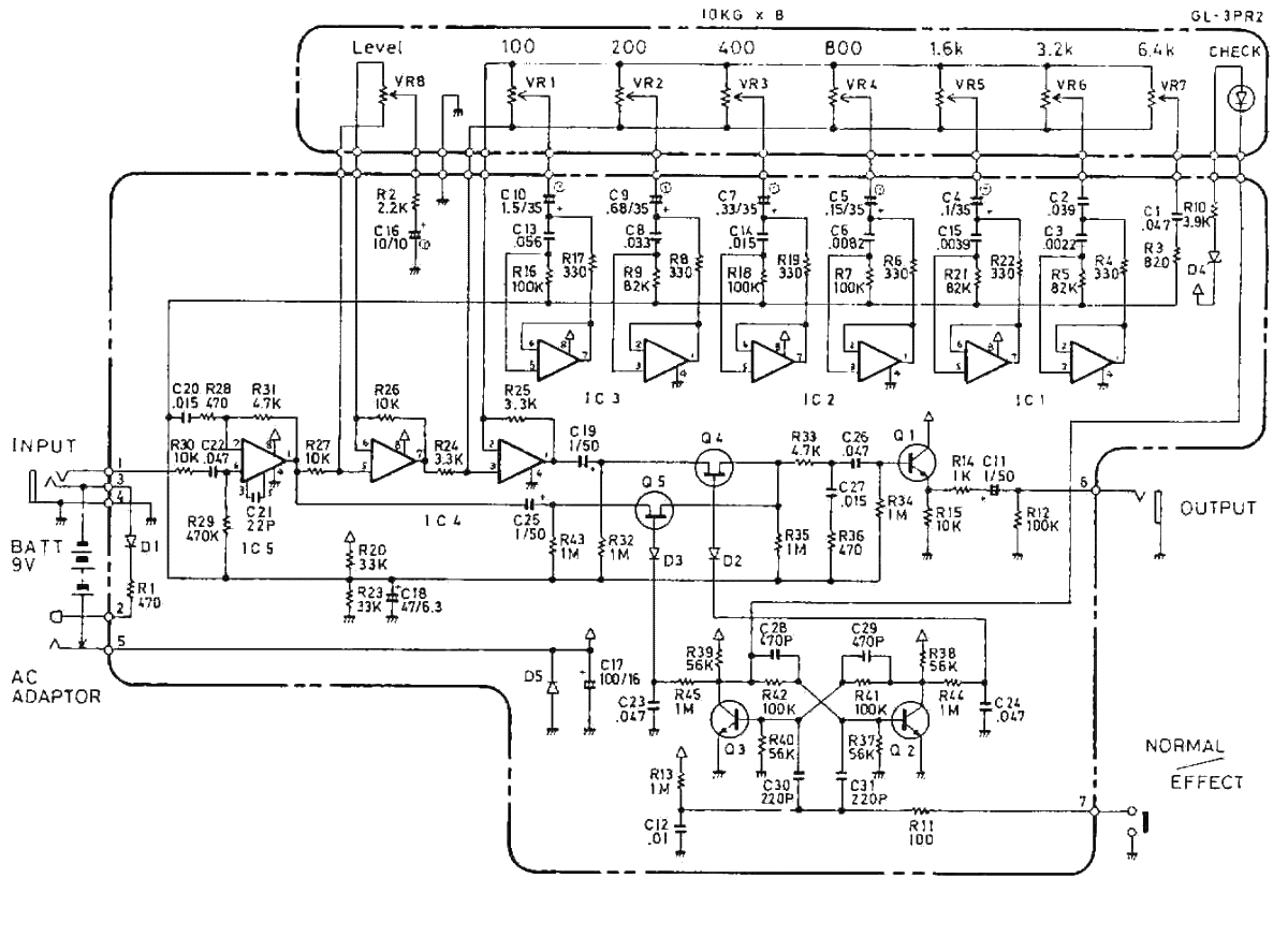 -Residual Noise Level: -100dBm (IHF-A Weighted, Typ.) -Equalizer Control: +/- 15Db -7 band EQ: 100Hz, 200Hz, 400Hz, 800Hz, 1.6kHz, 3.2kHz, 6.4kHz -Level Control: +/- 15 dB -Connectors: INPUT Jack, OUTPUT Jack, AC Adaptor Jack (DC 9V) -Power Supply: DC 9V Dry Battery (6F22/9V), AC Adaptor -Current Draw: 7mA (DC 9V) -AC Adaptor: ACA-Series or PSA-Series (new models with silver label) -Width: 70 mm -Depth: 125 mm -Height: 55 mm -Weight: 450g ICs, transistors and diodes used in the Boss GE-7 equalizer: -IC1, IC2,IC3: TL022CP dual operational amplifiers -IC4: uPC4558C dual operational amplifier -IC5: HA1457W preamplifier -Q1: 2SC732TM-GR NPN silicon transistor -Q2, Q3: 2SC945-P NPN silicon transistor -Q4, Q5: 2SK30ATM-Y N-channel JFET transistor -D1, D2, D3: 1S2473 diodes -D4: RD5.6EB3 500mW 5.6V Zener diode -D5: 1OE2 diode |