|
#1
February 20th, 2016, 03:34 PM
| |||
| |||
| MTDC Systems & Overvoltages
Sir I want the sample report on the Multi-Terminal HVDC System & overvoltage’s so can you tell me the same Hey buddy below I am givng you the report on the Multi-Terminal HVDC System below MTDC systems Report INTRODUCTION HVDC transmission systems designed and operated so far are point to point systems with two terminals (converter stations). A multiterminal DC (MTDC) system has more than two converter stations, some of them operating as rectifiers and others as inverters. The simplest way of building a MTDC system from an existing two terminal system is to introduce tappings. Parallel operation of converters and bipoles can also be viewed as multi terminal operation. Unlike in AC systems, the task of extending two terminal systems to multiterminal systems is not trivial. The complexities of control and protection increase considerably, and the use of HVDC breakers is generally required in the MTDC systems. In recent times, with growth in HVDC transmission, there could be more than one converter in proximity feeding same load area. The operational issues of such Multi-Infeed DC (MIDC) systems are similar to those of MTDC systems. Hence, MIDC systems are also discussed in this chapter. With recent advances in the emerging technology of VSC-HVDC transmission, the application of MTDC systems is becoming more attractive than before. POTENTIAL APPLICATIONS OF MTDC SYSTEMS Apart from tapping of power from existing two terminal systems, there are three specific areas of applications for MTDC systems. These are listed below: Bulk power transmission from several remote generating stations to several load centres. Here, each generating plant (or unit) is connected directly to a rectifier station thereby dispensing with the AC collector system. Similarly, a converter station at each load centre eliminates the need to build additional AC (or DC) lines for flexible energy exchange. An MTDC system has several advantages over the alternative of point to point systems. For example, consider a system of two generating stations and two loads as shown in Fig. 9.1. This is a radial system with two rectifiers and two inverters. For ensuring the same level of flexibility in energy exchange, three two terminal DC links will be required in addition to a link connecting the two receiving systems, which could be AC or DC (see Fig. 9.2). This would result in extra costs for the converter stations, lines and additional power losses in increased number of conversions. MTDC systems Report 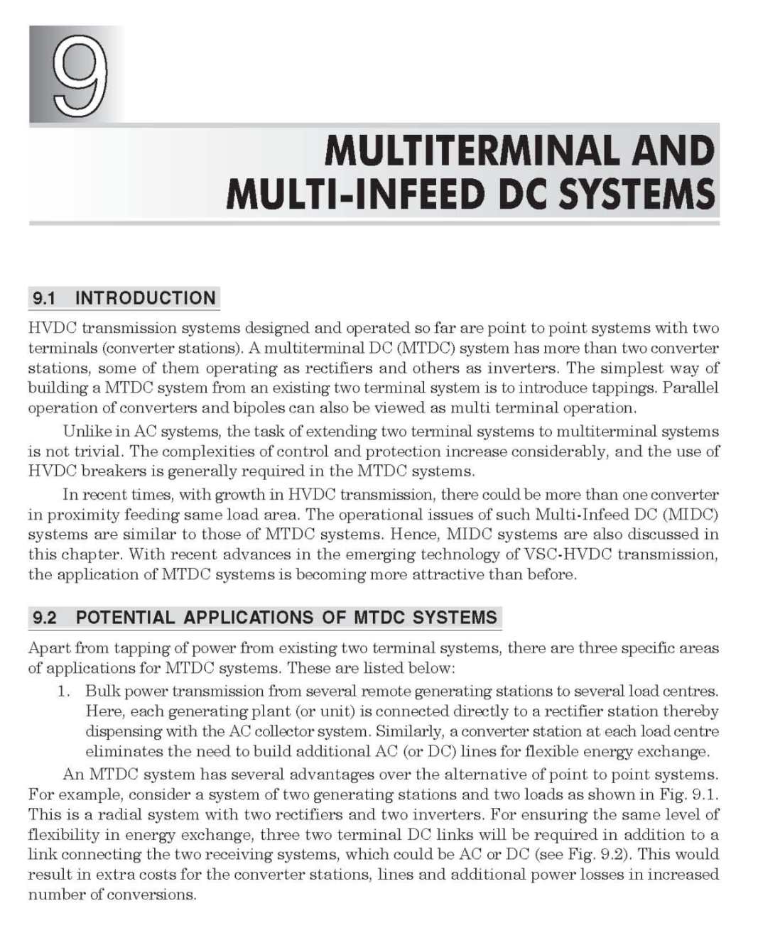 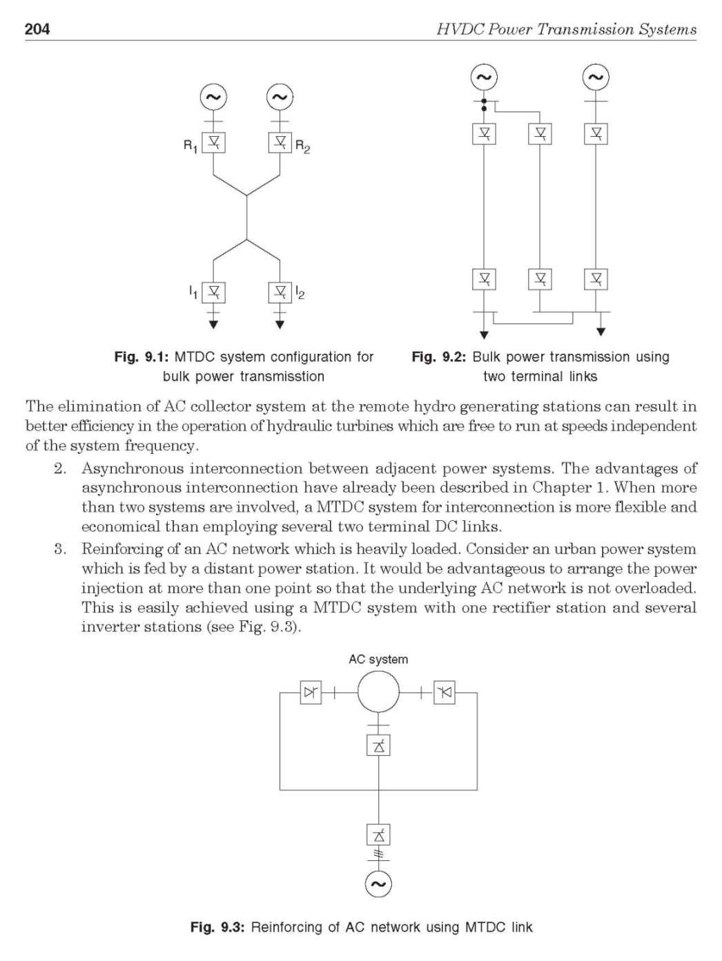    Last edited by Neelurk; April 3rd, 2020 at 11:29 AM. |